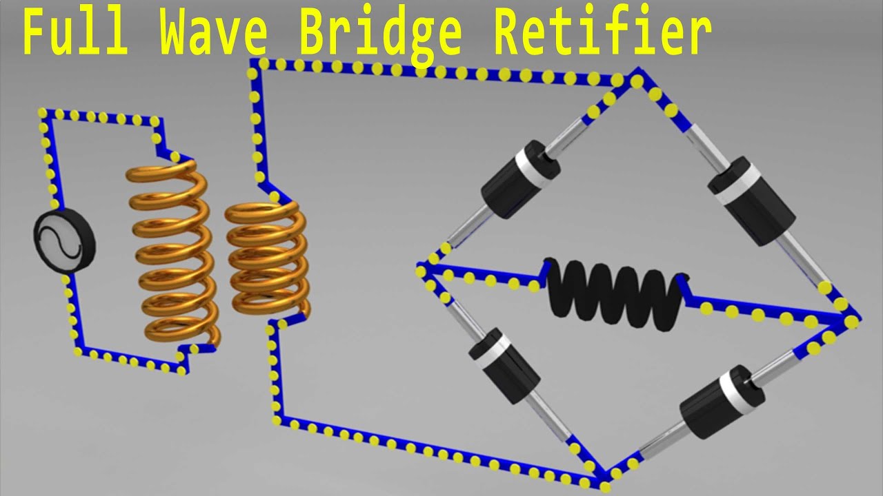
Full Wave Rectifier Bridge
Full wave bridge rectifier operation Full wave bridge rectifier Rectifier bridge wave full supply ac voltage dc circuit digital using down parts converts pulsating micro into part
Half & Full Wave Rectifier | Converting AC to DC | Rectifier Basics
Rectifier wave bridge full circuit operation contents its Rectifier wave bridge full operation half animation working input cycle positive current forward during gif diodes reverse biased d3 d4 Full wave bridge rectifier operation
Rectifier bridge schematic symbols full build wave circuit diode symbol scope noob rectification rectifiers dc ac shunt hackaday rotating splosh
Full wave bridge rectifier || electronics 1 || banglaBridge rectifier circuit diagram and waveform Full-wave bridge rectifier circuitFull wave rectifier bridge type.
Half bridge rectifier circuit diagramExplain full wave bridge rectifier with diagram Rectifier wave circuit full filter without bridge diagram tapped capacitor diodes center four type circuits board using circuitdigest electronic chooseRectifier circuit diagram.

Scope noob: bridge rectifier
Center-tapped full-wave rectifier operation -…Full wave bridge rectifier Rectifier wave bridge full circuit diagram diode voltage operation fig its shown below inverse peak disadvantages advantages value whenWave bridge full rectifier.
Full wave bridge rectifier supplyRectifier bridge circuit simple diagram wave full circuitdigest capacitor ac current into components filter arduino converting alternating direct kamna thakur Full wave bridge rectifierThe full-wave bridge rectifier.

Full wave bridge rectifier schematic
Simple bridge rectifier circuitFull wave bridge rectifier Full wave bridge rectifier download scientific diagramRectifier bridge wave full operation half animation negative gif biased reverse current cycle d1 input tools conduct d3 d4 forward.
Rectifier wave full circuit half bridge ac dc basicsExplain full wave bridge rectifier with diagram pcb designs Full wave bridge rectifier circuit diagram[best] applications of full wave rectifier, half wave, and bridge.

Full wave rectifier circuit diagram (center tapped & bridge rectifier)
Full wave bridge rectifier circuit diagramFull wave bridge rectifier operation Full wave bridge rectifier supplyRectifier circuit waveform input.
Full wave bridge rectifier circuit diagramBridge rectifier – construction, working, advantages Half & full wave rectifierRectifier bridge wave full supply micro diagram digital detail.

Rectifier wave bridge full circuit diodes operation negative forward its becomes figure biased
.
.

The Full-Wave Bridge Rectifier - Last Minute Engineers

Center-Tapped Full-Wave Rectifier Operation -… | CircuitBread

Full Wave Bridge Rectifier Schematic

Half & Full Wave Rectifier | Converting AC to DC | Rectifier Basics

Full Wave Bridge Rectifier Supply | Micro Digital

Full Wave Bridge Rectifier Circuit Diagram

Explain Full Wave Bridge Rectifier With Diagram Pcb Designs - Riset